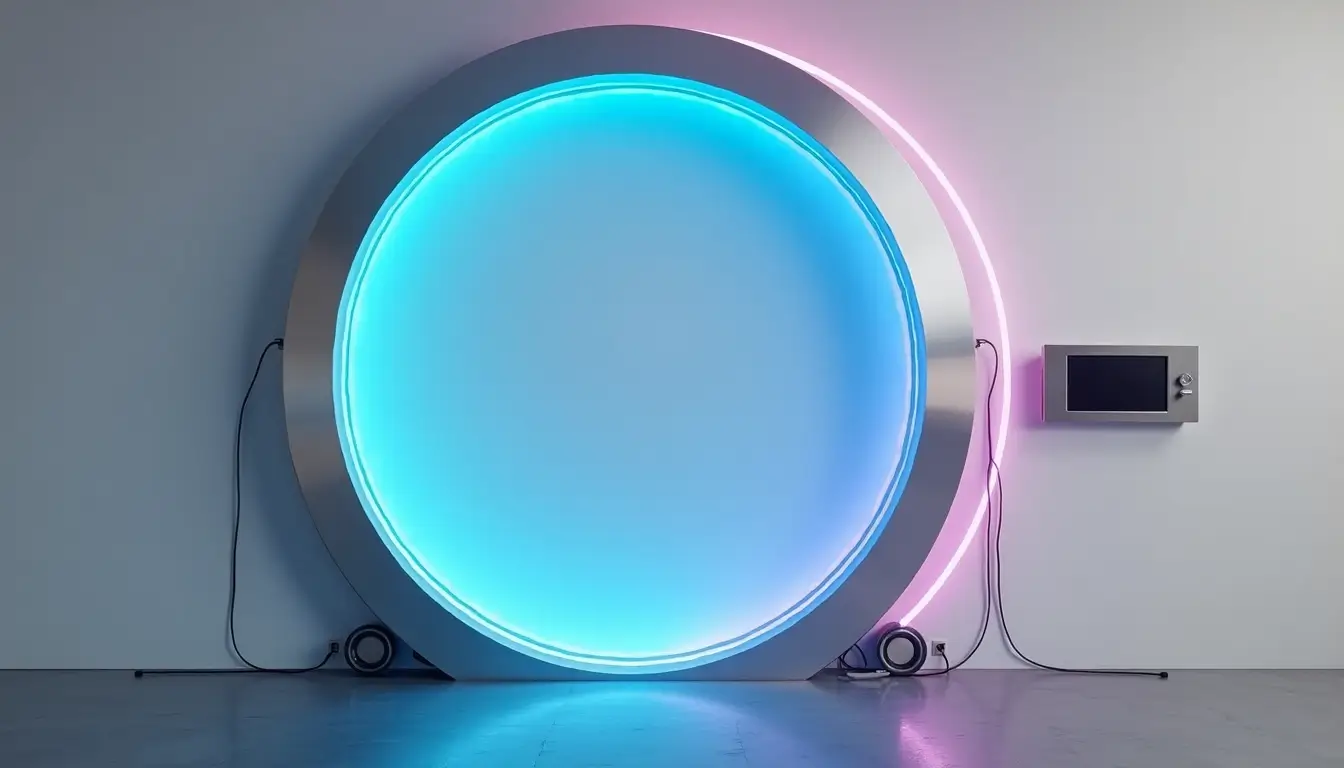
Magic portals have engaged people’s imagination for centuries. A techno gateway in walls now turns this fantasy into reality.
These modern portals combine advanced technologies like AR, AI, and IoT to create immersive experiences. LED lights, holographic projections, and digital elements can make a simple wall a technological masterpiece.
The possibilities extend beyond entertainment and affect everything from education to healthcare and communication. This guide will show you how to build your Techno Gateway that balances visual appeal with functionality, whether you’re tech-savvy or just starting with DIY projects.
Your wall can become a stunning technological portal.
Essential Materials and Tools for Your Techno Gateway
You must carefully select components and materials to build a functional and safe Techno Gateway.
Required Electronics and Components
Your gateway system’s core consists of essential electronic components. We used a Touch Board with pre-soldered headers and an Electrode Shield that allows quick connections. You’ll need twelve Electrode Pads and shielded cables with 3.5mm jack plugs. A microSD card with the reader and a micro USB cable power the system and help you program it.
Construction Materials and Tools
Quality construction materials create your gateway’s foundation. A solid plywood base works as the mounting surface. You’ll also need:
- Steel components to build the roof structure
- PVC or aluminium doors at access points
- Double-glazed windows as visual elements
- Cable management clips and marking sets
- Self-tapping and machine screws to mount everything
Safety Equipment Checklist
Your safety comes first when installing electronics. Insulated tools protect you from electrical shocks. A complete safety kit should have the following:
Your personal protective gear consists of safety glasses, gloves, and high-visibility clothing. Fire-resistant clothing provides extra protection while working with electrical parts. Keep a first aid kit close by to handle minor injuries quickly.
Thermal isolator clips provide excellent insulation and prevent cold spots that cause condensation. They come in sizes from 2″ to 8″ and support up to four square feet each. Store all components in a clean, dry space and use proper protective gear when handling them.
Planning Your Techno Wall System
A techno gateway’s success depends on careful planning and exact measurements.
Choosing the Ideal Wall Location
You need a central spot that maximizes visibility and user interaction. Walk through your space to find areas with high foot traffic and natural stopping points. The perfect location should have minimal visual distractions; viewers should see it clearly from different angles. The best spot is where people linger rather than pass by.
Measuring and Layout Guidelines
Design your wall system on 2-foot modules to maximize material use and reduce waste. Take multiple measurements at different points because walls might not be perfectly square, especially in older buildings. Advanced framing techniques let you space wall studs up to 24 inches in the centre. Load distribution works best when floor, wall, and roof framing members line up directly above each other.
Power and Wiring Requirements
The gateway system has specific power requirements. Basic gateway operations need 3.2W at 12V as standard power consumption. Here are the key power specifications:
- You can power the system through PoE (Power over Ethernet) or DC power sources
- You’ll need a 10 to 30 VDC power source with barrel connector compatibility
- The system works in temperatures from -40 to +80°C
Your wiring layout should effectively handle both power and data connections. The system needs network connectivity, and ethernet cables work best for stable communication. A battery backup system helps maintain uninterrupted operation during power outages.
The gateway works best when mounted at eye level, giving viewers a 5-7 second interaction window as they approach. Ensure all hardware connections meet minimum safety standards and complete the setup without live voltage.
Building the Gateway Framework
Your techno gateway’s framework acts as its backbone. You will need precise assembly and attention to detail.
Creating the Base Structure
Start by installing the bottom and top plates that make up your wall frame’s horizontal members. Next, add corner studs at each end and intersection studs where walls meet at 90 degrees. Place full-length studs at 24-inch intervals throughout the frame. The straightest studs work best for door and window openings to arrange your gateway components properly.
Installing Support Systems
Load distribution plays a key role in the support structure. The system will need secondary jamb studs beneath lintels. Depending on the span, you might need up to three support studs. To improve stability, install horizontal noggins at 1.350m spacing between vertical studs. Modern techno gateways use sheet bracing for extra rigidity, while traditional timber frames rely on diagonal bracing at 45 degrees.
Wiring and Cable Management
A well-managed cable system looks good and works efficiently. Your gateway system needs these specific wire types:
- Power cables: 6 AWG to 250 kcal for main supply terminals
- Communication lines: 24 AWG CAT5 or better for ethernet connections
- Ground wiring: 6 AWG to 2/0 with green or bare colouring
Place adaptable boxes (around 100mm) to end cables in one spot. Secure your cables with conduit clips or tie wraps. The bases should be screwed into the wall structure. All terminals must have a minimum rating of 75°C. Run cables between the insulation and drywall in the exterior walls. Use fish tape to guide wires through the framework.
A structured wiring approach works best. First, set up the main power routes, then create separate paths for low-voltage and communication cables. Include 3-block-wide crawlspaces on all sides to leave space for future maintenance. This setup makes modifications easy and keeps your gateway looking clean.
Installing Technology Components
Your gateway wall’s technological core comes alive when you carefully integrate lighting, sound, and control systems.
Setting Up LED Systems
SK6812 RGBW LED strips create the main visual element of your gateway. First, remove the factory terminals from the strips and prepare them for soldering. Then, peel off the backing tape and press the LED strips into their channels. RGBW technology gives you both RGB colours and an extra white LED, allowing you to create a wider range of lighting effects.
Sound System Integration
A MAX9814 microphone module is the heart of the sound system. It captures ambient sound and causes the LEDs to react to music and audio inputs. The microphone module must be connected to the control system through specific pins. Power distribution needs careful planning since each LED strip meter uses 18W of power at full brightness.
Control Panel Installation
The ESP32 microcontroller is your gateway system’s brain and runs WLED firmware to control Wi-Fi and sound reactivity. These components should go inside an electrical box to stay safe and organized:
- Power supply with 15A fuses for each power line
- ESP32 microcontroller with WLED firmware
- Signal adapter board to amplify data
The main power input connects to the power supply, and you’ll want to add an easy-to-reach switch in the live wire. Your final assembly needs three separate LED strips connected to pins D2, D4, and D16 on the ESP32. A signal adapter board helps prevent white flashing issues. You can make one by soldering three individual LEDs onto a perf board that connects straight to the ESP32’s data pin.
Your control panel’s power management needs close attention. Car fuse holders with 15A fuses protect each power line from high amperage when multiple LED strips run at full brightness. Ensure all connections stay secure in the electrical box, leaving enough room for proper ventilation and heat dissipation.
Programming Your Technology Gateway
Programming breathes life into your techno gateway and turns a static installation into an interactive masterpiece.
Simple Control Setup
To get Wi-Fi control and sound reactivity features, you’ll need to install the WLED firmware on your ESP32 microcontroller. Connect the ESP32 with your computer and upload the firmware through the serial port. The gateway needs an internet connection through ethernet, Wi-Fi, or cellular network.
The programming sequence follows these steps:
- Power on the system components
- Connect to the gateway Wi-Fi network (TEG-###)
- Access the web interface through a browser
- Log in with designated credentials
- Configure your settings
Creating Light Sequences
WLED firmware gives you many options to create captivating light displays. We started with simple patterns like the rainbow mode, which creates flowing colour transitions on your LED strips. Once you are skilled at basic sequences, you can move to interactive modes where tiles respond to touch by changing colours or triggering specific effects.
Your light sequences perform best when programmed using PWM (Pulse Width Modulation) control. The system processes these commands in cycles to control brightness precisely. For instance, a 50% brightness setting means the LED stays on for five cycles and off for five cycles in a ten-cycle period.
Sound Pattern Programming
Sound patterns add an exciting dimension to your gateway. The MAX9814 microphone module works with the FFT Arduino library to create audio visualization features. The system takes ambient sound through the microphone and converts audio signals into dynamic light patterns.
You can customize these elements in the programming interface:
- Audio sensitivity levels
- Visualization patterns
- Response timing
- Colour schemes
The system runs in multiple modes, from standalone patterns to music-reactive displays. You can create custom sequences and modify timing, intensity, and colour combinations through the programming interface. The control software lets you display various content types and synchronizes background videos with dynamic light shows and audio input.
Development tools help you create advanced programming with custom modes. You can build interactive games and patterns like checkers, tic-tac-toe, and memory games. On top of that, it lets you make immediate adjustments to fine-tune effects based on ambient conditions or specific needs.
Conclusion
A techno gateway turns ordinary walls into stunning portals that blend state-of-the-art technology with practical functionality. Anyone can build this innovative installation with careful planning, precise measurements, and the right components.
The path to success lies in following each step methodically. You’ll need to start with the right materials, build a solid framework, integrate technological components, and program interactive features. Your gateway system will operate when you pay attention to safety protocols and proper power management.
Simple light displays are just the beginning. This techno gateway works as an artistic centrepiece and a functional technological interface that can boost any space with its dynamic presence.
Your system needs regular connection checks, firmware updates, and proper ventilation to perform at its best. Consistent monitoring and creative programming will help your techno gateway deliver captivating experiences while expanding the possibilities of interactive wall installations.